Sound Filtering For The Masses
Version of the document: v0.5 (14 October 1999)
NOTE: this document will be expanded and updated whenever I got free time, someday it will reach the most complete level of information on the subject of sound filtering that a DSP programmer may wish (including for example automatic methods to design IIR filters starting from impulse responses, and everything one may need to write sound filtering applications). This tutorial has been originally written for a bunch of friends (tjena EMoon :) ) and the Amiga coders homepage http://come.to/amiga, but is not specific to the Amiga computers (or any other computer) in any way.
If you click here, you can download this whole tutorial (including sources, pics and all) and read it offline.
This page is best viewed at a resolution of 1024x768 pixels.
yeah, I could have written it even smaller than that, don't whine!
SOUND FILTERING FOR THE MASSES,
by Maverick (Fabio Bizzetti)
Have you ever wanted to make an audio filter? Sure you wanted.. or you
wouldn't be reading this. Since, as you see, I'm a really really magic
person, now I'll guess even the rest of the story, i.e. you looked for
tutorials, but found only unreadable ones full of boring equations,
complex variables, excess of theory, etc.. so if you just want to
filter the damn thing, you get lost inside that mess.. that probably at
the end, after all that theory-pain, doesn't even give you any usable
implementation!!
Well, I'll give you the implementations, but I'll also give you (if you
wanna read it, that is) some important theory background. I won't talk
about complex numbers, "poles", "zeros" and such.. that's too abstract
for me (and probably also for you), but some theory on the physics
behind filtering is not only useful, but also probably a pleasure to
read (unlike the abstract math concrete waste of time, for many :) ).
So, let's start with the theory.. you can skip this section if you wish,
and go directly to the implementations of IIR
and FIR filters, including the more general
Convolution. But if you read it it
won't hurt you, I promise.
What is filtering?
To cut it short, filtering is a time-domain (i.e. sample-based) technique
to modify something that belongs to rather another domain.. i.e. the
frequency domain. As you understand, those two domains are very different
each other.. but this doesn't mean that you can't pass from one domain to
the other, modify it, and go back to your favourite domain (which most
probably will be the time-domain, i.e. sample-based). That's what does
the famous "Discrete Fourier Transform" (i.e. DFT and the equivalent,
but faster and someway less flexible FFT), together with its inverse
(to go back to time-domain from frequency-domain) called IDFT (Inverse
Discrete Fourier Transform) and the faster but, again, someway less
flexible IFFT. We will talk more about Fourier Transforms later.
So, filtering in practice is the technique that we need to remove or boost
certain frequences in our sound sample. Like, for example, the so called
"loudness".. that is a boost of low and high frequences, not affecting the
middle ones. I'm sure you've heard in your life at least thousands times the
effect that loudness creates on your ears. But you sure want more than just
that.
As my grandpa never used to say, "To understand what is recursion, we've
first to understand what is recursion..". But you're lucky, understanding
filters is easier. :)
What is an impulse?
An impulse is what in sampled data would be represented by a sequence of samples that starts with a value different than zero (usually the float 1.0, for simplicity), and all the following values are always zero, instead. So, that's an impulse. The impulse is the magic door between the two worlds (time-domain and frequency-domain), so I'm sure you will never forget how an impulse looks like from now on. You'll need it.
What is the impulse response of a (linear) system?
Here we go.. When you want to measure, or analyze, the characteristics of a given filter (i.e. a routine that gives you an output sample for each input sample, modifies the spectrum of the whole sample, and that you run continuosly, for example in real time), all you have to do is to feed it an impulse, and then record what happens to the output.. that will not be just an impulse, but will be a long sequence of samples.. i.e. an impulse response. If it gave you back just the impulse you gave it in, it wouldn't be a filter. Out=In is not a filter, you know. So, first thing to learn: it is impossible to make any filter (besides artificial intelligence things that will see the light in some hundred years thanks to the work of some nephews of mine :D ) that filters your data without a "trail".. i.e. without creating some sort of short "echo".. or more properly "reverb". So short that you dont perceive it as a reverb, but that anyway blends your waveform at some extent.. i.e. filters it. This means that if in your synthesizer you wanna change waveform every cycle, whatever is the filter you're using, it will radically change your waveform, and if you pause your synth the output of the filter will not pause immediately, but some samples will go out until it will decay to zero. That's perfectly normal, and our ears dont hear any of this "reverb", as I said. Even more, it's a good thing.. because it's exactly what happens in the real world, and gives a natural sound. Even a computer cannot avoid this, although with FIR filters (read below) it can be kept lower than with the analogue-real world filters (implemented also on a computer, the so called IIR filters). But what you've to know is that passing from time-domain to frequency-domain (and viceversa) is not perfect.. it has always some limitations.. in this case the "time resolution".. i.e. you can't pretend from any filter to be quick in its response as light-speed. Neither if you upsample your sound 1000 times.. it won't change this limitation at all. In practice, this is not really a problem anyway.
What are the differences between IIR and FIR filters?
IIR means "Infinite Impulse Response", and as you may guess it is a true
analogue filter (even if it's simulated by a computer, it's still 100% an
analogue filter.. if you dont believe it, think that many IIR filters on
computer are converted straight from the real world electronic filters
counterparts). If you feed it an impulse, the output will be a
self-oscillation that will decay more and more, but theoretically will
never stop... it will stop just because you reached the limits that the
integer/fixed-point/floating point variable that holds it can represent.
FIR instead means "Finite Impulse Response", and is pretty digital, i.e.
FIR filters don't exist in analogue electronics, or in nature. As the
name suggests, when you feed an impulse to a FIR filter, the output will
be long n samples, after which it will be *completely* "silent".
>From this presentation, FIR filters seem less precise, and thus worse
copies of IIR filters. And this is true, but also FIR filters have
qualities that IIR filters can't achieve easily. So in some applications
you may prefer to use IIR filters, in other applications you will prefer
FIR filters. Understanding the real differences is important to choose
what kind of filter you want to implement/use for that specific task you
need. Basically, IIR/FIR filters have these pro's and cons:
IIR Pro: Doesn't require much CPU load, even if you want a small bandwidth (e.g. resonant filters).
FIR Con: Requires a lot of CPU load, expecially if you want a small bandwidth (e.g. resonant filters).
>From this, you already get that IIR's are more suitable for realtime, while FIR's are more suitable for non-realtime. A good point for IIR's.
IIR Pro: You can change the behaviour of the filter (e.g. the cut-off frequency and gain) changing/updating a relatively small amount of parameters in the function.
FIR Con: Changing the characterists of the filter means recalculating all of the filter's coefficients.. something that for long filters may be very time-consuming. But, anyway, long FIR filters are already time consuming by themselves.. so for non realtime uses this is not really a "Con".
>From the above is clear that if you want to make a sweeping filter (e.g.
a WahWah, or some 303-style resonant low-pass filters) then IIR filters
are more suitable, even not considering the more CPU-intensive nature of
FIR filters.
IIR Con: It's hard to design.. expecially the most complex ones, or high order ones.
FIR Pro: Whatever is the order and/or frequency response you want, FIR filters are damn easy to design.
Here an advantage for FIR's, but that applies mostly to non-realtime,
because of the last point (computation costs).
IIR Con: It's extremely hard to design an IIR filter that has linear phase response.
FIR Pro: It's damn easy to design a FIR filter that has linear phase response.
What is linear phase response? Well.. as the name suggests, it's when the
output keeps the correct phase information for all frequences.. something
that unfortunately all the generic IIR filters don't do. But don't worry..
phase information is not as useful as it seems: our ear in most of the
practical cases doesn't even notice a difference. Expecially when processing
real/natural sounds, as guitar sounds, or voice, or ambient, etc.. that
are already "phase random" by themselves. Different thing would be, for
example, the case of a very artificial sawtooth waveform. You could hear
the non-linear phase shift, then.. not a big deal, but audible anyway.
You may not want this, so use a FIR filter. Otherwise, if you wanted to
make an IIR filter with linear phase response, you would have to use one
or more "allpass filters" (i.e. IIR filters that don't alter the frequency
magnitudes at all, but modify the phase-shift at different frequences)
before/after your IIR filter, to correct someway its non linear phase
behaviour, and get it back to linear. Believe me, it's better to use FIR
filters then! It may even be computationally preferable in some cases,
let away the complexity.
What is convolution?
Convolution is a time-domain operation that lets us enter a foot into that
magic door I mentioned at the begin of the tutorial, i.e. the one between
time-domain and frequency-domain, still remaining really inside the
time-domain world. Do you remember what is an impulse? Do you remember what
is an impulse response? No? You're really a lazy lamer, pal! Well, anyway,
let's go on: one nice characteristic of the so called linear systems in
the discrete time-domain (as our filters used on our sound samples are)
is that a whole sample can be considered a train of individual impulses,
but at the end if you process a single impulse, or this whole train,
using the same algorithm, the result is still the right one.
So, let's imagine we got the impulse response of a filter we like.. i.e.
we don't even have its algorithm/routine, but we know how it looks like..
i.e. we've the impulse response it gave us back in response to a single
impulse. In practice, what we did then was to filter a single sample.
Now, being it a linear system, the impulse response's magnitude (of the
whole impulse response) will be directly proportional to the magnitude
of our original impulse.. so we can filter any single sample, whatever
it is. Either it was 1.0 or 0.3 or 0.9 or 1.4 or -128 or +32767 it
doesn't matter.. our impulse response magnitude will be directly
proportional to it. So, if you have an output buffer, a look-up-table
(containing the impulse response at e.g. a standard magnitude 1.0
of the impulse you used to create it), your output will be the same
look-up-table multiplied for the amplitude of the input sample. Now
take another input sample, increase your output pointer of 1 position,
and repeat the procedure.. adding this new magnified impulse response
to the previous output samples. Do it for the 3rd input sample, now to
the 3rd output sample position, and so on.. and you will have performed
convolution on your input sample, and got an output sample that is as
long as your input sample, plus the length of your look-up-table.
Hear the result.. filtering!! The soul of the filter that you stole
taking its impulse response now will live forever thanks to the
convolution you performed, and even if you dont have the filter routine,
you will get the filtering 100% as if you had that routine. Interesting?
That's how FIR filters work. A FIR is, after all, a recording (or a
simulation) of the impulse response of an IIR filter. These last ones
dont use convolution of course, but a different method I will explain
later. What you'll like to know now is that impulse responses are more
than just filters' output.. e.g. if you go into a cathedral, swear a
bit, then produce an impulse (for example popping a balloon) and
record the output (that hopefully won't contain any trace of your
swearing, but will contain only a nice reverb of that impulse), then
go home and perform convolution on some sound sample using that
impulse response you recorded there in the cathedral, you *will* hear
yourself into that cathedral at the position where the microphone was,
and your sample will be placed where the balloon was, and the reverb will
be 100% exactly as the one you would get if you were really into that
cathedral, playing samples instead of popping balloons (i.e. producing
an impulse). As you may intuite, if you even go stereo, you will get
some cool experience.. but don't forget that the 3D perception of
audio is due also to the shape of our outer ears.. so just using two
microphones resembling the head's ears won't give perfect 3D audio.. but
close to. If you use a dummy head with microphones that look like ears
and use the right materials (there are some in commerce) to emulate the
sound absorption properties of human heads/shoulders/etc.., you will get
really perfect 3D audio.. for that head, floor, shoulder and ears! That
is, 3D audio is an individual thing.. it varies from person to person,
that's why no generic method works well on everybody. I will give also
implementations of 3D audio later, for your happiness and this tutorial's
completeness.
Reverb is neither more nor less filtering, this implementation makes
use of a long FIR (in the order of seconds.. i.e. hundreds of thousands
samples.. not really for realtime!). The realtime reverberation units
that we can buy for our electric guitars and keyboards of course don't
have all that processing power, so they *try* to recreate a nice reverb
impulse response by using only special IIR filters.. long ones, of course.
The famous delay+feedback is nothing else than an IIR filter in practice.
Those reverb commercial units in practice use many of these in serie and
parallel, to recreate more complex reverberations.
So, if FIR filters use convolution, what do IIR filters use?
They use recursion.. and the more past samples they have to remember, the higher the order of the filter (e.g. 1st order, 2nd order, etc..). Normally for IIR filters you dont need anything more than that, but FIR filters (whose's order is measured by the number of samples that the impulse response they use has) are of course always (very) high order ones. For FIR filters used in sound filtering applications, orders like 32-256 or more are pretty normal. The perfect cathedral reverb example of above would need a FIR of about half million order. Not quite realtime.. but as perfect as it could really be.
What is a dB (decibel), and why do I need to know it?
linear = pow(10.0, dB/20.0); /* from decibels to linear */
dB = log10(linear)*20.0; /* from linear to decibels */[convincing text to be added]
Want an advice?
I know, you really like DSP stuff.. Want an advice? You've really to
subscribe to the Usenet newsgroups "comp.dsp" and "comp.music.research".
Also, you may want to buy some good books on DSP. In my experience, most
of them are excessively superficial.. just introduction books, and no
excellent book exists that covers every known DSP algorithm [if you know
any, please let me know - email
me].
Talking about "good books", someone suggested me (but I don't own it..
so I can't tell you if it's really good or not) "A Digital Signal
Processing Primer, with Applications to Digital Audio and Computer
Music" by Ken Steiglitz. Another book somebody else suggested me is
"Discrete Time Signal Processing" by Alan V. Oppenheim and Ronald W.
Schafer.
Talking about "bad books", I feel like to advice you not to buy
"A Programmer's Guide To Sound" by Tim Kientzle, because you
probably already know about DSP more than the author wrote in
that book. That's it.. most (if not all) books on DSP leave you
with more unanswered questions than you asked, so, at the end, the
best thing is to subscribe to those two Usenet newsgroups, and ask
for help there about the most advanced algorithms (e.g. tube simulation,
Constant-Q transforms, etc.. etc..).
What kind of basic IIR filter types are there?
First it's better to explain what are the parameters of these filters:
Frequency is the frequency at which the filter has to work.
Depending on the type of filter you're using, the meaning of this parameter
changes. For lowpass/highpass filters it's the cutoff frequency, for
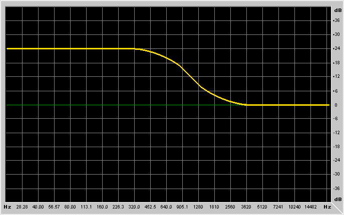
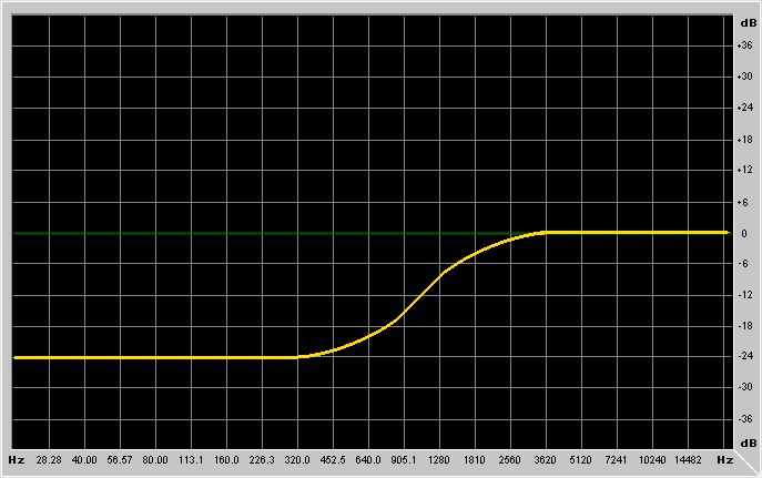
low-shelving/high-shelving it's the center of the "transition band",
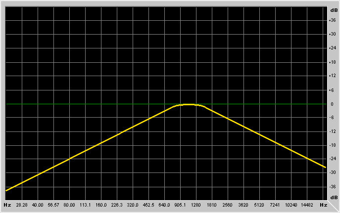
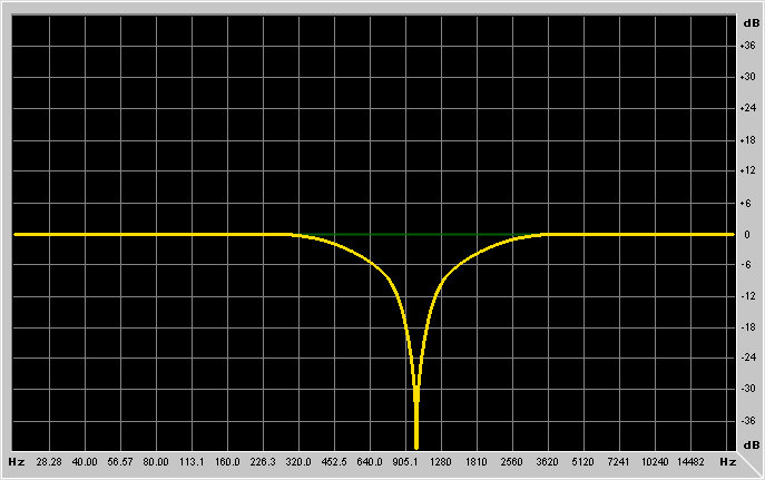
for bandpass/notch/peaking filters it's the resonance frequency.
Q is the selectivity of the filter, and is equal to the
Frequency/Bandwidth. The Bandwidth is defined as the distance (in Hz)
between the two points with 3dB of difference with the gain at the
frequency at which the filter is set to operate (bandpass case);
or the distance between the two points at dB-Gain/2 (peaking case).
The higher the Q, the more selective is the filter. Note that high
values for Q will slightly change the behaviour of lowpass/highpass
filters, making them have a superior to flat gain before the cut-off
frequency. A lowpass filter with high Q becomes a kind of hybrid
between a bandpass and a lowpass. Use the provided code to get
(and the graph) the magnitude response of the filters, to get a
better idea of how all these parameters affect the filtering [to be added].
Gain is the gain of the filter. For lowpass/highpass/bandpass and
notch it's an overall gain (like an amplifier cascaded to the filter), while
for low-shelving, high-shelving and peaking filters it's the gain in the
region where the filter is operating.
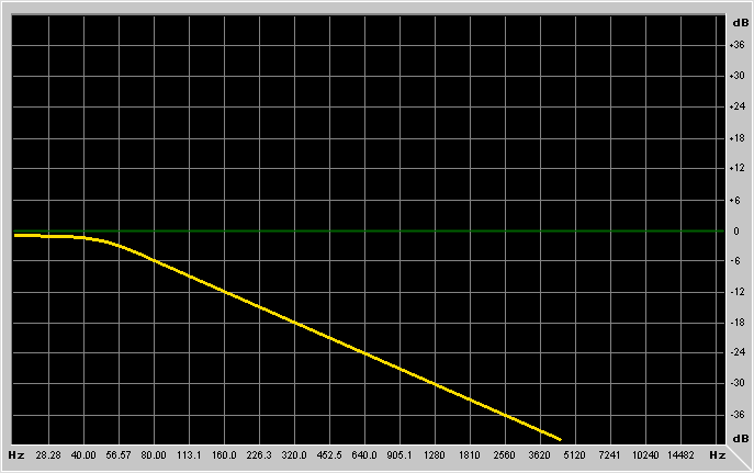
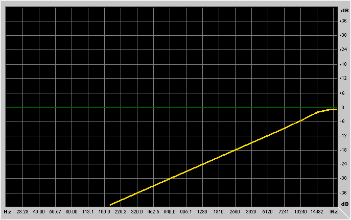
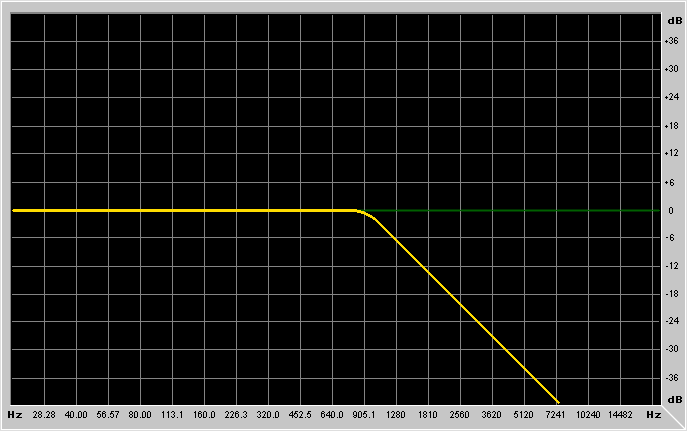
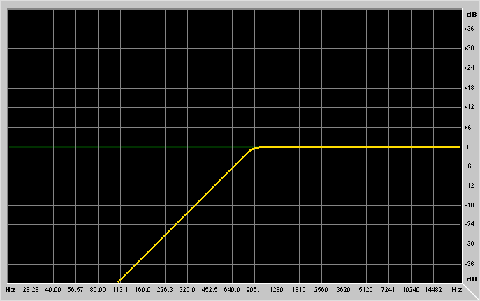
It's probably better to show example graphs:

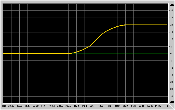
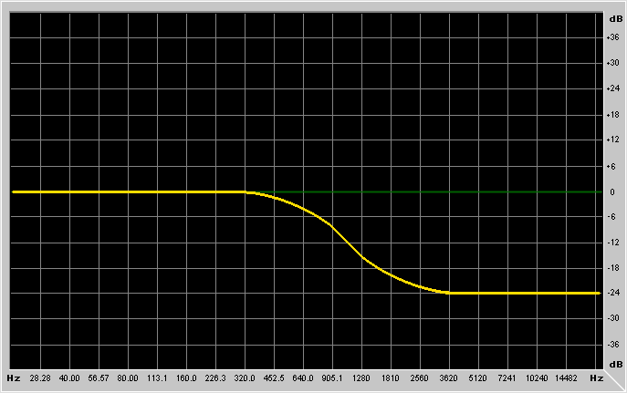
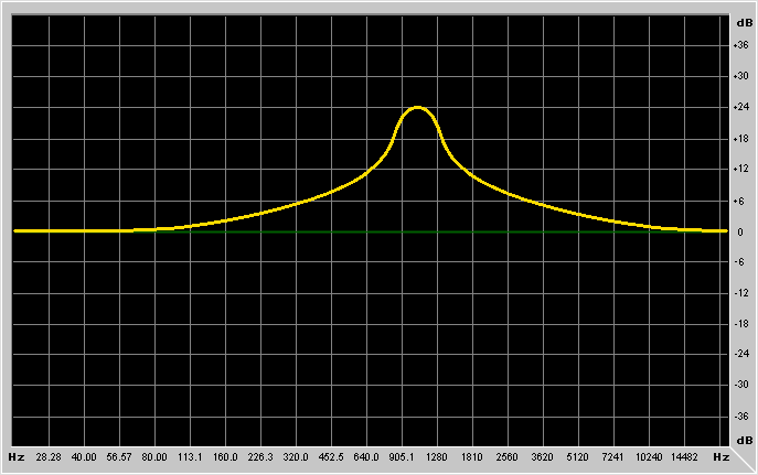
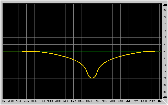
What kind of basic FIR filter types are there?
None. On a FIR you simply specify the exact response in every part of the spectrum. The higher the order of the FIR filter, the more the detail you can specify. E.g., on a 64th order FIR filter, the whole spectrum is made of 64 elements that you can adjust freely. FIR filters, however, see the spectrum in a linear way.. not logarithmic as in all the example graphs of above. This means that higher frequences are a waste of CPU power, while you hardly get enough detail in lower frequences. Why? Because the human ear works in a logarithmic way (both about frequences and, for the matter, also amplitudes).
How do I implement IIR filters?
Here I will cover only first-order and second-order IIR filters. Higher
orders are commonly built using these two types as "cell blocks" that you
then combine freely (in serie or in parallel). You don't need anything
more than that to build any IIR filter of any complexity.
First order IIR filters exist only of two types: lowpass and highpass
(ok, and other weird/unusual filters you don't really care about, right
now). In analogue electronics, the first order lowpass/highpass filters
are equivalent to e.g. simple RC (resistor-capacitor) passive circuits.
The lowpass implementation looks like this:
in Basic syntax, if you're still using your Commodore64 as a realtime DSP (my most sincere congratulations, btw):
10 PRINT "NOT ENOUGH CPU POWER FOR THAT"
20 GOTO 10
30 REM I DONT GUARANTEE THE FUNCTIONALITY OF THE BASIC VERSION
the same identical thing in C/C++ syntax instead:
input = [your actual input sample];              /* for realtime, it would be the ADC */
output = a*input + a*previnput + b*prevoutput;   /* and this would be the DAC */
previnput = input; prevoutput = output;
Run these 4 lines of above in a loop, and you got your filter. As you may guess, first you've anyway to calculate a & b.. but then you won't need to recalculate them anymore, unless you want to change the filter's cutoff frequency in a dynamic way; in this case you'll have to recalculate these 2 coefficients every time.. ideally in the same loop of above (or use a look up table). Now how to calculate these 2 coefficients:
b = atan( Pi * CutoffFrequency / SampleRate); b = -(b - 1.0) / (1.0 + b);
a = 0.5 * (1.0 - b);
The "sample rate" is, ehmmm... if you don't know it, you better kill yourself within 1/44100 of second from now. "Pi" is 3.141592653589793... The "cutoff frequency" is the frequency at which the filter cuts of 3dB the input signal. The maximum achievable filtering with a first order filter is anyway 6dB/octave. It's not much, but it's already enough for many musical applications. You can put several filters in serie or in parallel if you want more filtering than that.
input = [your actual input sample];              /* for realtime, it would be the ADC */
output = a*input - a*previnput + b*prevoutput;   /* and this would be the DAC */
previnput = input; prevoutput = output;
and the coefficients:
b = atan( Pi * CutoffFrequency / SamplingFrequency); b = -( b - 1.0) / (1.0 + b);
a = 0.5 * (1.0 + b);
Declare some global variables and #define the number of filter units we want: double SampleRate; /* set it to e.g. 44100.0 (Hz) */ #define Pi 3.141592653589793 /* constant */ #define Pi2 6.283185307179586 /* constant */ #define maxfilterunits 10 /* set it to the max number of filter units you may use (10 units = use units 0..9) */Trivial, wasn't it?
Now the function: double FilterCell(unsigned long Unit, double Input, double Frequency, double Q, double Gain, unsigned long Type) { static double i1[maxfilterunits], i2[maxfilterunits], o1[maxfilterunits], o2[maxfilterunits]; /* temporary variables */ static double a0[maxfilterunits], a1[maxfilterunits], a2[maxfilterunits]; /* coefficients */ static double b0[maxfilterunits], b1[maxfilterunits], b2[maxfilterunits]; /* coefficients */ static double f[maxfilterunits]; /* last Frequency used */ static double q[maxfilterunits]; /* last Q used */ static double g[maxfilterunits]; /* last Gain used */ static unsigned long t[maxfilterunits]; /* last Type used */ /* --------------------------------------------------------------- */ double Output,S,omega,A,sn,cs,alpha,beta,temp1,temp2,temp3,temp4; /* -- check if frequency, Q, gain or type has changed.. and, if so, update coefficients */ if ( ( Frequency != f[Unit] ) || ( Q != q[Unit] ) || ( Gain != g[Unit] ) || ( Type != t[Unit] ) ) { f[Unit] = Frequency; q[Unit] = Q; g[Unit] = Gain; t[Unit] = Type; /* remember last frequency, q, gain and type */ switch (Type) { case 0: /* no filtering */ b0[Unit] = pow( 10.0, Gain / 20.0 ); /* convert from dB to linear */ break; case 1: /* lowpass */ Gain = pow( 10.0, Gain / 20.0 ); /* convert from dB to linear */ omega = ( Pi2 * Frequency ) / SampleRate; sn = sin( omega ); cs = cos( omega ); alpha = sn / ( 2.0 * Q ); a0[Unit] = 1.0 / ( 1.0 + alpha ); a1[Unit] = ( -2.0 * cs ) * a0[Unit]; a2[Unit] = ( 1.0 - alpha ) * a0[Unit]; b1[Unit] = ( 1.0 - cs ) * a0[Unit] * Gain; b0[Unit] = b1[Unit] * 0.5; break; case 2: /* highpass */ Gain = pow( 10.0, Gain / 20.0 ); /* convert from dB to linear */ omega = ( Pi2 * Frequency ) / SampleRate; sn = sin( omega ); cs = cos( omega ); alpha = sn / ( 2.0 * Q ); a0[Unit] = 1.0 / ( 1.0 + alpha ); a1[Unit] = ( -2.0 * cs ) * a0[Unit]; a2[Unit] = ( 1.0 - alpha ) * a0[Unit]; b1[Unit] = -( 1.0 + cs ) * a0[Unit] * Gain; b0[Unit] = -b1[Unit] * 0.5; break; case 3: /* bandpass */ Gain = pow( 10.0, Gain / 20.0 ); /* convert from dB to linear */ omega = ( Pi2 * Frequency ) / SampleRate; sn = sin( omega ); cs = cos( omega ); alpha = sn / ( 2.0 * Q ); a0[Unit] = 1.0 / ( 1.0 + alpha ); a1[Unit] = ( -2.0 * cs ) * a0[Unit]; a2[Unit] = ( 1.0 - alpha ) * a0[Unit]; b0[Unit] = alpha * a0[Unit] * Gain; break; case 4: /* notch */ Gain = pow( 10.0, Gain / 20.0 ); /* convert from dB to linear */ omega = ( Pi2 * Frequency ) / SampleRate; sn = sin( omega ); cs = cos( omega ); alpha = sn / ( 2.0 * Q ); a0[Unit] = 1.0 / ( 1.0 + alpha ); a1[Unit] = ( -2.0 * cs ) * a0[Unit]; a2[Unit] = ( 1.0 - alpha ) * a0[Unit]; b0[Unit] = a0[Unit] * Gain; b1[Unit] = a1[Unit] * Gain; break; case 5: /* lowshelf */ /* "shelf slope" 1.0 = max slope, because neither Q nor bandwidth is used in */ /* those filters (note: true only for lowshelf and highshelf, not peaking). */ S = 1.0; /* used only by lowshelf and highshelf */ A = pow( 10.0 , ( Gain / 40.0 ) ); /* Gain is expressed in dB */ omega = ( Pi2 * Frequency ) / SampleRate; sn = sin( omega ); cs = cos( omega ); temp1 = A + 1.0; temp2 = A - 1.0; temp3 = temp1 * cs; temp4 = temp2 * cs; beta = sn * sqrt( ( A * A + 1.0 ) / S - temp2 * temp2 ); a0[Unit] = 1.0 / ( temp1 + temp4 + beta ); a1[Unit] = ( -2.0 * ( temp2 + temp3 ) ) * a0[Unit]; a2[Unit] = ( temp1 + temp4 - beta ) * a0[Unit]; b0[Unit] = ( A * ( temp1 - temp4 + beta ) ) * a0[Unit]; b1[Unit] = ( 2.0 * A * ( temp2 - temp3 ) ) * a0[Unit]; b2[Unit] = ( A * ( temp1 - temp4 - beta ) ) * a0[Unit]; break; case 6: /* highshelf */ /* "shelf slope" 1.0 = max slope, because neither Q nor bandwidth is used in */ /* those filters (note: true only for lowshelf and highshelf, not peaking). */ S = 1.0; /* used only by lowshelf and highshelf */ A = pow( 10.0, ( Gain / 40.0 ) ); /* Gain is expressed in dB */ omega = ( Pi2 * Frequency ) / SampleRate; sn = sin( omega ); cs = cos( omega ); temp1 = A + 1.0; temp2 = A - 1.0; temp3 = temp1 * cs; temp4 = temp2 * cs; beta = sn * sqrt( ( A * A + 1.0 ) / S - temp2 * temp2 ); a0[Unit] = 1.0 / ( temp1 - temp4 + beta ); a1[Unit] = ( 2.0 * ( temp2 - temp3 ) ) * a0[Unit]; a2[Unit] = ( temp1 - temp4 - beta ) * a0[Unit]; b0[Unit] = ( A * ( temp1 + temp4 + beta ) ) * a0[Unit]; b1[Unit] = ( -2.0 * A * ( temp2 + temp3 ) ) * a0[Unit]; b2[Unit] = ( A * ( temp1 + temp4 - beta ) ) * a0[Unit]; break; case 7: /* peaking */ A = pow( 10.0, ( Gain / 40.0 ) ); /* Gain is expressed in dB */ omega = ( Pi2 * Frequency ) / SampleRate; sn = sin( omega ); cs = cos( omega ); alpha = sn / ( 2.0 * Q ); temp1 = alpha * A; temp2 = alpha / A; a0[Unit] = 1.0 / ( 1.0 + temp2 ); a1[Unit] = ( -2.0 * cs ) * a0[Unit]; a2[Unit] = ( 1.0 - temp2 ) * a0[Unit]; b0[Unit] = ( 1.0 + temp1 ) * a0[Unit]; b2[Unit] = ( 1.0 - temp1 ) * a0[Unit]; break; } } /* -- filter loop: if you don't change the parameters of the filter dynamically, ~only this code will be executed. */ switch (Type) { case 0: /* no filtering */ Output = b0[Unit]*Input; break; case 1: /* lowpass */ case 2: /* highpass */ Output = b0[Unit]*Input + b1[Unit]*i1[Unit] + b0[Unit]*i2[Unit] - a1[Unit]*o1[Unit] - a2[Unit]*o2[Unit]; break; case 3: /* bandpass */ Output = b0[Unit]*Input - b0[Unit]*i2[Unit] - a1[Unit]*o1[Unit] - a2[Unit]*o2[Unit]; break; case 4: /* notch */ Output = b0[Unit]*Input + b1[Unit]*i1[Unit] + b0[Unit]*i2[Unit] - a1[Unit]*o1[Unit] - a2[Unit]*o2[Unit]; break; case 5: /* low shelving */ case 6: /* high shelving */ Output = b0[Unit]*Input + b1[Unit]*i1[Unit] + b2[Unit]*i2[Unit] - a1[Unit]*o1[Unit] - a2[Unit]*o2[Unit]; break; case 7: /* peaking */ Output = b0[Unit]*Input + a1[Unit]*i1[Unit] + b2[Unit]*i2[Unit] - a1[Unit]*o1[Unit] - a2[Unit]*o2[Unit]; break; } o2[Unit]=o1[Unit]; o1[Unit]=Output; i2[Unit]=i1[Unit]; i1[Unit]=Input; /* update variables for recursion */ return(Output); }
How do I implement convolution?
Now I'll show you my source to perform Convolution. It's very versatile,
and suitable for realtime, meaning that it works on a sample by sample
basis, and not on a whole buffer.
Use it this way:
Output = Convolve(Unit, Input, IR_Pt, IR_Len);
Output is the output sample you're gonna get (and feed e.g. to a DAC).
Unit is the convolution unit you are referring to (like in an array).
It's a kind of object-oriented programming, not using C++ classes though. For
a single convolution unit, you would always use only unit 0. But if you want
to use more than one convolution unit, then you would have to duplicate the
source a number of times necessary to have all the convolution units you need
(remember: the convolution code needs to remember past samples, so buffers
are needed), or I could have provided pointers to buffers for the past
samples, etc..), but my solution has been the simplest and most comfortable
one. You have to #define maxconvolveunits as the number of units you wanna
use. 1 is the minimum, of course (meaning you use only unit 0).
Input is your input sample.. for example coming directly from an ADC.
IR_pt is the memory pointer to the impulse response. It's a classic
byte pointer, although it points to doubles.
IR_len is the impulse response length, in samples (not in bytes!).
Being samples of the type double, each sample is 8 bytes long. But you've
to specify the number of samples, here, not bytes.
#define maxconvolveunits 10                            /* max number of convolution units we may use */

double Convolve(unsigned long Unit, double Input, char *IR_pt, unsigned long IR_len) {
   static double *buf_pt[maxconvolveunits];
   static unsigned long buf_pos[maxconvolveunits];
   static unsigned long lastir_len[maxconvolveunits];
   double output; unsigned long n; double *ir,*bf,*bfs,*bfe;
   /* ---------------------------------------------------------------------------------------------- */
   if (IR_len!=lastir_len[Unit]) {          /* length of impulse response changed: reallocate buffer */
      if (buf_pt[Unit]!=0) free((char*)buf_pt[Unit]); /* frees a previously allocated buffer, if any */
      buf_pt[Unit]=(double*)malloc(IR_len<<3);                             /* allocates a new buffer */
      memset((PTR)buf_pt[Unit],0,IR_len<<3); buf_pos[Unit]=0;       /* reset the state of the buffer */
      lastir_len[Unit]=IR_len;
   }
   /* ---------------------------------------------------------------------------------------------- */
   ir=(double*)IR_pt+IR_len-1; bfs=buf_pt[Unit]; bfe=bfs+IR_len;
   *(bfs+buf_pos[Unit]++)=Input; if (buf_pos[Unit]>=IR_len) buf_pos[Unit]=0;
   bf=bfs+buf_pos[Unit]; output=0.0;
   for (n=0; n<IR_len; n++) { output+=(*ir--)*(*bf++); if (bf>=bfe) bf=bfs; }
   return(output);
}
How do I implement FIR filters?
[to be added]
NOTE: (if you're in a hurry and can't wait the next version of the tutorial,
dammit! ;) ). FIR filters are implemeted just using convolution (refer to the
"theory" part for explanation), so the source I'll write will be an extension
to that of convolution: i.e., I will add code to calculate the desired impulse
response. For that, I've to write before IFFT code, and windowing code, so it
will be for the next version of the tutorial.. I've no time right now and this
tutorial's release has been delayed enough.
[to be added]
buh?
Here I will talk about some miscellaneous topics related to sound filtering:
EnvelopeFollower = (EnvelopeFollower * 0.999) + (0.002 * fabs(input));Input is considered normalized to 1.0 (i.e. -1.0 to 1.0, not e.g. -32768 to 32767).
wahfreq = 5000.0 * EnvelopeFollower * EnvelopeFollower;
if (wahfreq < 500.0) wahfreq = 500.0;
if (wahfreq > 5000.0) wahfreq = 5000.0;
output = FilterCell(0, input, wahfreq, 10.0, 20.0*EnvelopeFollower, 3);
This is an example of my Auto-Wah (and my realtime DSP effects program) in action.. with my electric guitar: guitarcat.mp3
Final words..
That's all for now.. if there're enough requests, when I have some free
time I can write more tutorials on effects such as distortion (tube-like
one too, not just stupid clipping), chorusing, pitch shifting, ring
modulation, noise gating, dynamics compression/expansion/limiting, etc..
Since I'm not a rich person (coding games for the Amiga never made me
become one, not that it was really important to become one anyway),
I wrote by myself all my electric guitar DSP effects using my WC
(a.k.a. PC) and its soundcard in realtime.. without any latency
(besides some microseconds for the delta-sigma ADC/DAC conversion
and buffering, but no DMA delay) on a program that I regularly use
and enjoy. So I saved a lot of money from buying pedal effects, and
I also customized my own effects to get my own "sound" and style,
including a warm tube-amp simulation I'm perfectioning day after day.
Someday I will release this program (as shareware probably), but right
now I'm busy on a much more important project, still audio/music related
(an original approach to physical modelling, to model real instruments
with total realism).
The biggest problem of the realtime DSP program is the lack of support of
soundcards. The manufacturers nowadays don't release the specifications
to program the hardware directly (as I need to get ~zero latency.. please
forget Win32 and/or DirectX.. they suck, expecially as latency), so I
ended up buying an old 16bit WSS card for which I had the hardware
programming docs, and that was 100% WSS compatible (an Opti931 based card),
unlike the Yamaha719 which is not 100% WSS compatible, and doesn't let you
read/write the ADC/DAC directly.
I also wrote the drivers to support the old 8/16bit SoundBlaster cards,
but for such a task these cards really suck, not being able to perform
16bit->16bit fullduplex, but only 8bit->16bit or 16bit->8bit.. both
are very noisy, with a very poor signal to noise ratio (48dB best case,
which is not even realistically achieved).
So, if you got hardware programming docs (just the ADC/DAC, no midi or
synthesizer info is needed) of good soundcards (like e.g. the SB Live),
I would be glad to support them.
I hope that this tutorial was written in a clear, but still concise
way, and that it solved your filtering doubts and some of your menthal
problems. If it solved also some of your dietary problems, please write
me! It's incredible how useful filters can be.
You cannot reach me via email at the address
[email protected],
but you can reach me at any/every other email address in this world.
So mail yourself, and you'll be sure that I'll receive your mail.
BTW: if you receive an email that you sent to me, don't worry, it's
perfectly normal. Forget it.
Ciao, and happy composing/playing/coding/listening,
FabI/O "Maverock" Bzzzt
Maverick